BauderSOLAR G Light - Design Drawings & Installation Changes
Update Design Drawings and Installation Methodology for Improved Clarity and Appearance
This contractor update is issued to notify all relevant parties of updates to BauderSOLAR G Light design drawings and installation methodology. These changes have been introduced to improve drawing clarity, reduce on-site ambiguity, and enhance the overall appearance of the installed solar PV array.
Plan Drawing Clarity
The following changes have been made to the design drawings for BauderSOLAR G Light to improve clarity and component identification.
| Complete Design example | |
| Previous | The previous drawings lacked clear panel orientation and sufficient visual differentiation between panels, anchor boards, and inserts, leading to reduced clarity and potential onsite confusion.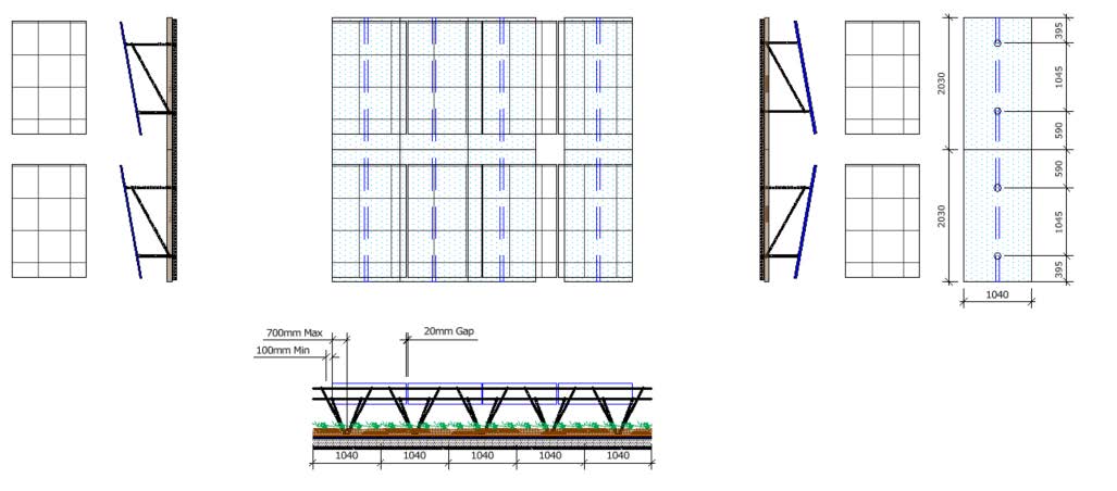 |
| Improved | 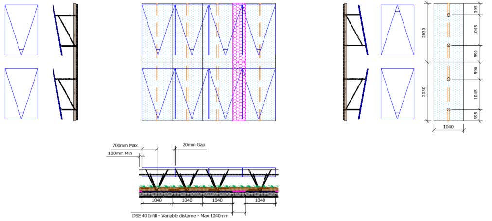 Panels are now shown in blue with a directional arrow to clearly indicate module orientation and layout intent, while base rails (yellow parallel lines) are now in a higher contrast colour. Magenta shading denotes DSE40 infill (non-anchor) boards, clearly distinguishing them from anchor boards within the layout. Panels are now shown in blue with a directional arrow to clearly indicate module orientation and layout intent, while base rails (yellow parallel lines) are now in a higher contrast colour. Magenta shading denotes DSE40 infill (non-anchor) boards, clearly distinguishing them from anchor boards within the layout. |
Improvements to Layout and Installation Methodology
These changes improve overall array appearance and reduce the number of BauderSOLAR DSE40 (Anchor Boards) required. Whilst also minimising on site confusion relating to rail overhang and panel capacity.
Previous Installation:
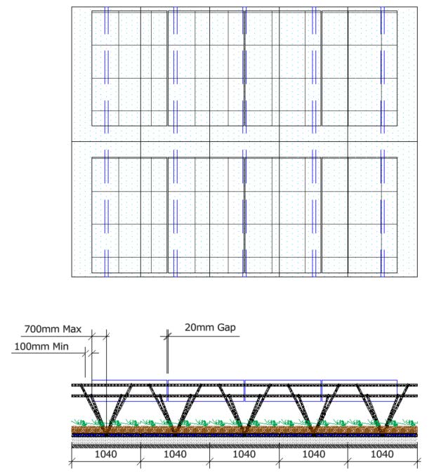
Anchor boards were previously installed side by side beneath every panel, causing unnecessary extension of BauderSOLAR MTR (module rails) and BauderSOLAR VT 545&745 (V brackets) beyond the last module and, in some cases, leading to additional panels being incorrectly added.
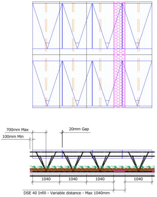
Under the revised methodology, DSE40 anchor boards are spaced where possible depending on row length to achieve a consistent finish, reduce visible rail and bracket overhang, and improve clarity. Any resulting gaps are infilled with standard DSE40 drainage board and are clearly indicated in magenta on the drawings (as shown below).
| Previous | Improved |
 |  |
BauderSOLAR DSE40 (Anchor Board) Dimensions & Alignment
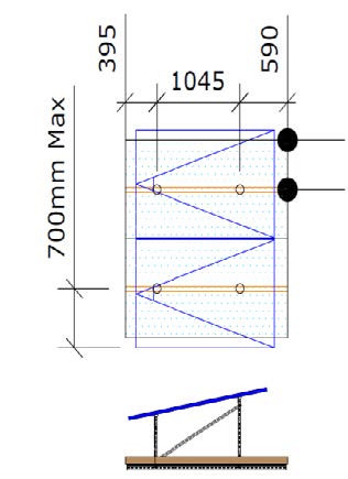
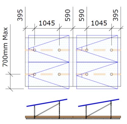
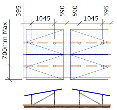
The BauderSOLAR DSE40 (Anchor Board) includes pre formed holes to allow connection of the BauderSOLAR BS 2/4 (Base Rails) and BauderSOLAR VT 545 & 745 (V Brackets). Hole spacing is orientation specific and must follow the project drawings. The images below show DSE40 dimensions, placement, and module overhang allowance.
| BauderSOLAR DSE40 Dimensions | North Orientation |
 |  |
| East West Orientation | |
 | |
BauderSOLAR MTR (module support rail) Installation orientation
The module support rail must be installed with its long face oriented toward the lowest edge of the panel.
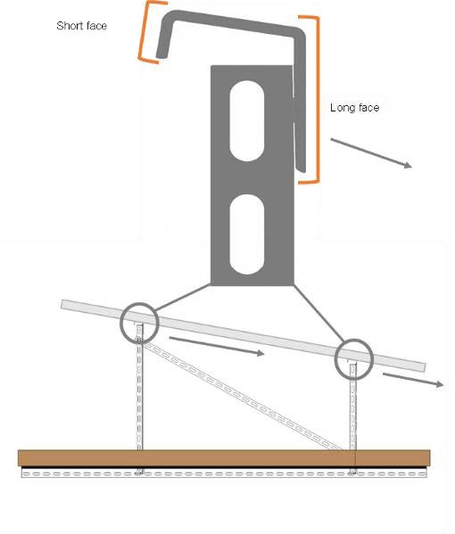
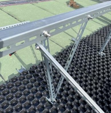
BauderSOLAR MTR (module support rail) orientation on BauderSOLAR VT 745 ( long V-carrier unit).
Publish date: 27/04/2026
This update confirms improvements to BauderSOLAR G Light drawings and installation methodology, with all changes implemented in the installation manual and reflected in future design drawings.
Thank you for taking the time to review this update. Should you have any questions or encounter any issues relating to these changes, please do not hesitate to get in touch.
Kind regards,
Angharad Wynne-Golledge
Product Manager – Solar PV
Bauder Limited
Email: [email protected]
Phone: 07353 159605